Introduction to Three-Way Switches: How To Wire A Three Way Switch
Three-way switches are a common feature in residential electrical systems, enabling control of a single light fixture from two different locations. This is a significant improvement over a single switch, which only allows for on/off control from a single point. Understanding their function and wiring is crucial for proper electrical work.
Three-way switches are employed to control a single light from two different locations, such as a hallway light that can be turned on or off from either end. This setup allows for more convenient lighting control compared to using a single switch, especially in longer hallways or rooms with multiple access points.
Three-Way Switch Circuit Operation
Three-way switches differ fundamentally from single-pole switches. A single-pole switch has two terminals; one connects to the hot wire, and the other connects to the light fixture. A three-way switch, on the other hand, has three terminals. The additional terminal allows for the connection of the other three-way switch and the light fixture. This arrangement creates a different current path, enabling control from multiple points.
Comparison to Single-Pole Switches
A crucial difference lies in the wiring configuration. A single-pole switch directly controls the light. In contrast, a three-way switch requires a second switch and a specific wiring arrangement to function correctly. The second three-way switch serves as a secondary control point for the same light. This complex wiring pattern ensures that turning the light on or off from either switch will effectively change the light’s state.
Circuit Diagram
The following diagram illustrates a three-way switch circuit:
| Wire | Description |
|---|---|
| Hot Wire (Black) | Carries electrical current from the electrical panel to the circuit. |
| Load Wire (White) | Connects to the light fixture; completes the circuit for the light to work. |
| Common Wire (Red/Orange) | The wire that connects the two three-way switches. |
| Three-way Switch 1 (left) | Provides a path for the current when the switch is activated. |
| Three-way Switch 2 (right) | Provides a path for the current when the switch is activated. |
| Light Fixture | The device that uses the electricity to produce light. |

Diagram: A basic three-way switch circuit. The hot wire (black) connects to the electrical panel. The load wire (white) connects to the light fixture. The common wire (red/orange) connects both three-way switches. Each three-way switch has three terminals: common, traveler, and traveler.
Components of a Three-Way Switch Circuit

Three-way switch circuits provide a convenient way to control a light fixture from two different locations. Understanding the components and their functions is crucial for proper installation and troubleshooting. These circuits are common in homes and commercial spaces, offering flexibility in lighting control.
The three-way switch circuit relies on a specific arrangement of components to facilitate control from multiple points. The key components, including switches, wires, and the load (light fixture), each play a critical role in the circuit’s operation. The correct wiring is essential to ensure the circuit functions as intended.
Key Components
The fundamental components in a three-way switch circuit are the three-way switches themselves, connecting wires, and the light fixture (load). Each component plays a vital role in the circuit’s operation.
- Three-Way Switches: These switches have three terminals, allowing for a connection that enables control from two separate locations. Each switch connects to the other switch via a wire, and both switches connect to the load via wires.
- Connecting Wires: Appropriate gauge wires are used to connect the switches and the load. The wiring must be capable of carrying the current needed by the load. Carefully chosen wire colors facilitate easy identification and proper wiring.
- Load (Light Fixture): The load is the light fixture or other electrical device controlled by the three-way switches. It has a connection point to accommodate the wires coming from the switches.
Wiring Comparison: Single-Pole vs. Three-Way
The wiring configuration differs significantly between single-pole and three-way switch circuits. A clear understanding of these differences is essential for proper installation.
| Component | Single-Pole Switch | Three-Way Switch |
|---|---|---|
| Number of Terminals | Two | Three |
| Control Points | One | Two |
| Wiring Configuration | A single switch controls a single load directly. | Two switches control a single load using a common wire. |
| Common Wire | N/A | Essential for communication between switches. |
Typical Wire Colors in Three-Way Circuits
Using consistent wire colors helps ensure proper connections in a three-way switch circuit. This standardized approach reduces the chance of errors during installation.
| Wire Color | Typical Function |
|---|---|
| Black | Hot (supply) wire |
| White | Neutral wire |
| Red | Switch leg/common wire |
| Other colors (e.g., Green, Yellow, Blue) | Ground wire (typically green or bare) |
Wiring Diagrams and Procedures
Three-way switch circuits provide flexibility for controlling a single light fixture from two different locations. Proper wiring is crucial for safety and functionality. Incorrect wiring can lead to electrical hazards and malfunctions. This section details wiring diagrams, connection procedures, and important considerations for a safe and effective installation.
Wiring Diagrams
Various configurations of three-way switch circuits exist, but the fundamental components remain the same: two three-way switches, one light fixture, and appropriate wiring. The diagrams below illustrate common configurations, emphasizing the crucial connections between the switches and the load (light fixture). Each diagram visually represents the flow of electricity from the power source through the switches to the light.

How to wire a three way switch – Diagram 1: This wiring diagram depicts a standard three-way switch circuit. Note the common connection point between the two switches, which is essential for the circuit’s functionality.

Diagram 2: This diagram illustrates a three-way switch circuit with a different configuration, demonstrating that various layouts are possible, each serving the same purpose. Pay attention to the switch and load connections.
Connecting Wires
Correct wire connections are paramount to a functioning and safe circuit. Use the appropriate wire gauge and type as specified in electrical codes for the specific application. Ensure all connections are secure and insulated to prevent electrical hazards. The neutral wire, the hot wire, and the switch wires must be correctly identified and connected.
Neutral Wire Connection
The neutral wire, typically white or gray, completes the circuit path, allowing current to return to the power source. It should be connected to the corresponding neutral terminal on both the switch and the light fixture. Ensure a secure connection to prevent any potential gaps or breaks.
Hot Wire Connection
The hot wire, usually black or red, carries the electrical current from the power source. It should be connected to the corresponding hot terminal on the switch and the light fixture. This connection ensures that the power reaches the light fixture to operate it.
Switch Wire Connection
The switch wires, typically black and white, connect the switches to each other and the load. Correct identification of these wires is crucial for proper circuit operation. One wire connects to one switch, and the other wire connects to the other switch.
Wire Gauge and Type
Using the correct wire gauge and type is critical for safe and reliable operation. Thinner wires can overheat and cause fire hazards. Thicker wires, conversely, may not be necessary for the circuit’s load. Electrical codes specify the appropriate wire gauge for different situations. Consult local electrical codes for the specific requirements for the location of the installation.
Installation Procedure
The following table Artikels the steps for installing a three-way switch circuit.
| Step | Procedure |
|---|---|
| 1 | Identify the hot, neutral, and ground wires from the electrical panel. |
| 2 | Connect the hot wire to the appropriate terminal on both switches and the light fixture. |
| 3 | Connect the neutral wire to the corresponding terminal on both switches and the light fixture. |
| 4 | Connect the switch wires according to the wiring diagram. |
| 5 | Secure all connections and ensure proper insulation. |
| 6 | Test the circuit to verify proper operation. |
Troubleshooting Common Wiring Issues

Troubleshooting three-way switch circuits can often be challenging, but a systematic approach can significantly reduce the frustration. Understanding the common wiring errors and their causes is crucial for effective diagnosis and repair. This section will guide you through identifying, diagnosing, and rectifying these issues.
Common Wiring Errors in Three-Way Switch Circuits
Identifying potential errors in three-way switch wiring is essential for efficient troubleshooting. Incorrect connections or reversed polarity can lead to a non-functional circuit. Common errors include incorrect wire connections, reversed wire connections between the switches and the load, and incorrect wiring of the neutral wire (if applicable).
Causes of Wiring Errors
Wiring errors in three-way switch circuits often stem from misinterpretations of the wiring diagram or a lack of attention to detail during installation. Incorrect wire identification, improper wire stripping, and incorrect connection points can all contribute to the problem. Inaccurate readings of the electrical panel or incorrect wire identification can also contribute to issues.
Diagnosing a Non-Functional Three-Way Switch Circuit
A systematic approach to diagnosing a non-functional three-way switch circuit involves a methodical evaluation of the circuit components and their connections. First, verify that the power supply to the circuit is intact and the circuit breaker is not tripped. Next, check for proper wire connections at both switches and the load. Ensure that the wires are properly stripped and connected to the appropriate terminals. Examine the wiring diagram to verify the correct wire connections and compare them to the actual connections in the circuit. Inspect the switch mechanism for any signs of damage or malfunction.
Troubleshooting Steps for a Non-functioning Three-Way Switch Circuit
- Power Check: Ensure the power supply is on and the circuit breaker is not tripped. A tripped breaker is a simple, yet often overlooked, cause of a non-functioning circuit. Verify the circuit breaker associated with the switch is functioning correctly. A non-functional breaker will require resetting the breaker.
- Visual Inspection: Carefully examine the wire connections at all points in the circuit, including the switches and the load. Look for any loose or damaged wires. Ensure that the wires are correctly connected to the corresponding terminals. Any exposed wires are a safety hazard. Proper wire insulation should be intact at all points.
- Wiring Diagram Comparison: Compare the actual wiring connections with the wiring diagram to identify any discrepancies. Incorrect wiring can lead to a malfunctioning circuit. Carefully scrutinize the connections to verify that they match the diagram. Note the position and orientation of the wires at all connections.
- Switch Mechanism Check: Inspect the switch mechanism for any signs of damage or malfunction. A faulty switch can be the source of the problem. Ensure the switch operates as expected.
Example of a Faulty Wiring Diagram and its Correction
| Faulty Diagram | Corrected Diagram |
|---|---|
|
(Illustrative description of the faulty diagram, highlighting the error. For example: “The diagram shows the hot wire connected to the common terminal on both switches, which is incorrect for a three-way switch circuit.”) |
(Illustrative description of the corrected diagram, highlighting the correction. For example: “The corrected diagram shows the hot wire connected to the traveler terminals on one switch and the load wire on the other, ensuring the proper three-way configuration.”) |
Safety Precautions and Considerations

Working with electrical wiring necessitates meticulous attention to safety protocols. Ignoring these precautions can lead to serious injuries or property damage. This section Artikels crucial safety measures to ensure a safe and successful wiring project.
Proper safety procedures are paramount when dealing with electrical systems. Failure to adhere to these guidelines can have severe consequences, ranging from minor shocks to potentially fatal electrical accidents. Understanding and implementing these precautions is essential for both novice and experienced DIYers.
Importance of Power Shut-Off
Ensuring the power supply is disconnected before commencing any electrical work is absolutely critical. This prevents accidental shocks and electrical hazards. A live circuit poses a significant risk, even with seemingly minor tasks. Always verify that the power is completely off at the circuit breaker or fuse box before handling any wires.
Safe Use of Electrical Tools and Equipment
Using appropriate electrical tools and safety equipment is vital. This includes using insulated tools, gloves, and safety glasses. These precautions help to prevent electrical shocks and other injuries. Ensure all tools are in good working condition and properly grounded to prevent electric shocks. Using damaged or faulty tools can compromise safety.
Risks of Incorrect Wiring
Incorrect wiring can lead to a variety of hazards. Short circuits, overheating, and electrical fires are potential outcomes. A poorly wired circuit can cause damage to the electrical system and pose a significant fire risk. This underscores the importance of careful planning and adherence to wiring diagrams.
Seeking Professional Help
If you lack the necessary knowledge or experience, seeking professional assistance is always recommended. Attempting to tackle complex wiring jobs without adequate expertise can be dangerous and lead to costly mistakes. Electricians possess the knowledge, training, and tools to ensure safe and efficient installations. This proactive approach can prevent potential hazards and ensure a compliant and durable electrical system.
Advanced Configurations and Applications

Three-way switch circuits offer flexibility beyond basic on/off functionality. This section delves into various configurations, including circuits with multiple switches, lights, or the integration of dimmer switches, along with wiring considerations for diverse electrical fixtures. Understanding these advanced setups empowers homeowners and electricians to manage lighting in more complex layouts effectively.
Multiple Switches and Lights
Multiple switches controlling a single light or multiple lights are common in larger spaces or areas with multiple entry points. This configuration allows for independent control from different locations. Wiring these configurations follows the same fundamental principles of three-way switches but expands on the number of connections.
- Multiple Lights: A single three-way switch circuit can control multiple lights. Each light will require its own set of wires connected to the common wire from the switch loop. This setup allows you to control all lights from multiple locations.
- Multiple Switches: Multiple three-way switches can control a single light. Each switch will be part of the three-way circuit loop. This setup allows for control from different locations, and the placement of each switch will determine the lighting conditions.
Wiring Diagrams for Multiple Lights and Switches
Detailed wiring diagrams are crucial for complex setups. These diagrams visually represent the connections between the switches, lights, and the electrical panel. They Artikel the paths current takes through the circuit, ensuring correct operation.
| Component | Connection |
|---|---|
| Switch 1 | One wire connected to the light fixture, one wire to the common wire of the second switch |
| Switch 2 | One wire connected to the light fixture, one wire to the common wire of the first switch |
| Light Fixture | One wire connected to each switch |
Three-Way Switch with a Dimmer Switch, How to wire a three way switch
Integrating a dimmer switch into a three-way circuit is achievable. A dimmer switch will require a specific wiring configuration that will manage the variable voltage to the light fixture. This will often necessitate the use of a specific dimmer switch that is compatible with three-way circuits.
- Compatibility: Not all dimmer switches are compatible with three-way circuits. Ensure the dimmer switch is explicitly labeled as suitable for three-way circuits.
- Wiring Modifications: The wiring modifications for a dimmer switch will vary based on the type of dimmer switch used. Consult the manufacturer’s instructions for specific wiring diagrams and procedures.
Specific Installation Scenario
Consider installing a three-way switch circuit in a hallway. The circuit will control one light fixture from two locations. Wiring will connect the two switches in a three-way loop and the light fixture to the common wire from the switch loop. Ensure the light fixture is appropriately wired to receive the current.
Receptacles and Fixtures
Wiring methods for different types of receptacles and fixtures vary slightly, primarily concerning the number and type of wires needed for the fixture.
- Recessed Lighting: Recessed lighting fixtures might require different wire configurations than traditional pendant or surface-mounted lights. Check the manufacturer’s specifications for the correct wiring approach.
- Ceiling Fans: Ceiling fans, which are frequently controlled by a single switch, will need a different wiring approach compared to three-way switches, as they may use different types of electrical connections.
Visual Aids and Examples

Visual aids play a crucial role in understanding complex wiring procedures. Illustrations and diagrams effectively communicate the steps involved, minimizing the risk of errors and facilitating a clearer comprehension of the electrical pathways. This section provides detailed descriptions of various visual aids, ranging from step-by-step wiring procedures to examples of different wiring configurations and materials.
Step-by-Step Wiring Procedure Illustrations
Visual representations of the wiring process, broken down into sequential steps, are highly beneficial. These illustrations will display the connections between the wires, the switch components, and the load. Each step should clearly indicate the specific actions required, including which wires to connect to which terminals, and the order in which connections should be made.
- Step 1: Identifying Components – A clear image should show the different components of the three-way switch circuit, such as the switches, the receptacles, and the connecting wires. Labels on the image will clearly identify each component, ensuring that users understand the parts of the system.
- Step 2: Preparing the Wires – An illustration should depict the proper method of stripping the insulation from the wires, ensuring a clean cut. Different types of wire strippers should be shown, with clear indications of the appropriate stripping length for each wire type.
- Step 3: Connecting the Wires to the Switches – The image will show the correct wiring connections to the switch terminals, clearly indicating the common (or hot), traveler, and neutral wire connections. A close-up view of the switch terminal connections would be useful.
- Step 4: Connecting the Wires to the Receptacle – A similar illustration will show the proper connections to the receptacle terminals, highlighting the hot, neutral, and ground connections. The image should indicate the use of appropriate wire connectors or wire nuts.
- Step 5: Testing the Circuit – The illustration should demonstrate how to check the circuit’s functionality after completing all the connections. A simple circuit tester should be shown for checking voltage and continuity.
Three-Way Switch Configurations
Visual examples showcasing different three-way switch configurations are essential. These configurations will demonstrate various scenarios, including those involving multiple switches controlling a single load, and how the wiring varies based on the layout.
- Standard Configuration – An image depicting a standard three-way switch circuit should be provided. This should show the typical wiring setup, highlighting the use of traveler wires connecting the switches.
- Long Runs – Illustrations showcasing long runs of wiring between the switches and the load will be useful. This will demonstrate how to properly manage wire lengths and maintain adequate electrical conductivity.
- Multiple Load Configurations – Visual representations of wiring for multiple loads controlled by a single three-way switch circuit should be included. This will show the connections to the additional loads.
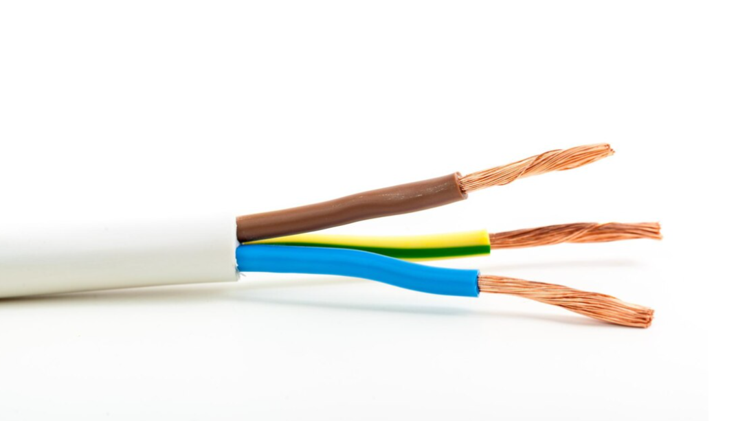
Wire Identification and Function
Visual aids demonstrating how to distinguish different wire colors and their functions are important. This will help users correctly identify the hot, neutral, and ground wires, as well as the traveler wires in a three-way switch circuit.
| Wire Color | Function | Description |
|---|---|---|
| Black | Hot (or Live) | Carries current from the power source to the load. |
| White | Neutral | Completes the circuit path for the current to flow back to the power source. |
| Green/Bare | Ground | Provides a safe path for fault currents to flow to the earth, preventing electric shock. |
| Red/Other Colors | Traveler | Connects the two switches, allowing the circuit to be switched on or off from either location. |
Electrical Circuit Flow Illustrations
Visualizing the flow of electricity in a three-way switch circuit is crucial. These illustrations should use diagrams to trace the electrical current’s path through the circuit from the power source to the load, and back to the power source. This will highlight how the current flows through the traveler wires when either switch is activated.
- Switch Closed/Open – Images showing the circuit with the switches in both the closed and open positions will illustrate how the current path changes based on the switch’s position. This will help users understand the different configurations and how the circuit operates.
- Complete Circuit Path – A diagram showing the complete circuit path, including the power source, switches, load, and return path, will visually represent the electrical flow.
Wiring Material Examples
Visual representations of various wiring materials and their appropriate use in three-way switch circuits are beneficial. This section will showcase different types of wire insulation, wire gauges, and connectors.
- Wire Insulation Types – Illustrations of different wire insulation types, such as PVC, Teflon, and others, highlighting their properties and suitability for various applications. This will help users choose the appropriate wire for their specific needs.
- Wire Gauge Illustrations – Visual representations of different wire gauges, with clear labels indicating their amperage ratings and appropriate use in different situations. This will ensure users choose the correct wire gauge for their application.
- Wire Connectors and Nuts – Images depicting various types of wire connectors and wire nuts, illustrating how to properly secure connections and prevent loose connections. This will help users understand the importance of proper wire termination.
Questions Often Asked
What are the typical wire colors used in three-way switch circuits?
Common wire colors include black (hot), white (neutral), and red (switch leg). However, color codes may vary depending on local electrical codes. Always verify the specific colors used in your region.
What if one of my three-way switches isn’t working after installation?
Several reasons can cause a three-way switch to malfunction. Check for loose connections, ensure the correct wire pairings, and verify the power supply is turned off. If the issue persists, consult a qualified electrician.
How do I wire a three-way switch with a dimmer switch?
Wiring a three-way switch with a dimmer switch requires special wiring techniques to accommodate the dimmer’s load. Refer to specific instructions for the dimmer switch model. Consult a professional if you’re unsure.